Requirements
The design of a modern replacement instrument panel for the upgrade and refurbishment of an old vehicle required better management of vehicle sensors and functions than was provided for in the 1980s wiring. As a modern recreational vehicle it required more than simple cabin lights operated by door switches and a handful of bulbs to indicate simple faults.
The vehicle included an electric fridge and induction hob, mains power, modern digital radio with handsfree facilities, USB charging, central door locking, 240V mains power from an inverter for double-insulated appliances, and a range of other internal lights and equipment, all of which required different treatment when the vehicle was being used for camping as opposed to just being driven from day-to-day, when the fridge, water pump and hob could be left unpowered and the radio, and USB charge points could go off with the ignition switch for example. The internal lighting needed to be linked to switches, and also to the doors, but capable of being switched on and off from the overhead bed panel.
A separate set of batteries, linked to the starter battery only when the ignition was on, ensured that the main battery could not be completely discharged by leisure activities. Both these banks of batteries were also charged from a 360W roof-mounted solar panel and MPPT converter, ensuring that the vehicle would be capable of being left for long periods without being driven, even with leisure equipment running.
In terms of vehicle instrumentation, the old analogue gauges were to be replaced by modern digital ones, with dimmable backlight and warning lights whose brightness could be varied for daytime and night-time use depending by whether vehicle headlights were on or not, and a more comprehensive selection of engine sensors were installed to provide more signals to a larger instrument panel.
Many of these functions were linked in complex ways. Although such complexity is currently widely implemented in modern cars, they are controlled by dedicated microprocessor-based management units. The task was to design and build a dedicate controller to implement the required set of functionality as a one-off supply because the requirements are bespoke to this vehicle.
Design Considerations
A major requirement was that the unit be suitable for automotive use, so while it appears on the face of it that the task would be easily performed by a modern off-the-shelf processor, the reality is not so straightforward, as the solution required dozens of digital inputs and outputs, all of which had to be resilient to an automotive environment.
In this regard, the term ‘automotive’ covers more than simply mechanical and electrical suitability. It would be possible to design such a system using a microprocessor solution, and for a commercial project this would have been a perfectly feasible path, however this would not have been a cost-effective solution for a one-off design for several reasons:
It would have required the design of a custom PCB and electronics, which is a time-consuming task and almost inevitably involves more than one iteration. Automotive electronics, even those fitted within a vehicle cabin, are subject to a wide range of temperatures and humidity, and electrical interference and spikes. Testing such a system for reliability would have been a significant task.
The other, perhaps larger, issue with a microprocessor-based solution would have been the ability to effect repairs. No replacement parts would exist, therefore it would have been necessary to produce at least two, or possibly three complete units, as the Lowest Replaceable Unit (LRU) would have effectively been the entire controller.
Even though the system is not safety-critical, the loss of functionality which would include instruments, would be a major problem, so a replacement unit would have had to be carried in the vehicle. Once it had been used it would have been necessary to produce another spare. It was therefore a solution which would have been a ‘never-ending’ job, and would have relied on it being possible to obtain the components to make and program another spare in, say, ten year’s time.
Based on this, and the fact that almost all the functions required are logic operations, it was decided to base the design on an electromagnetic solution.
Design Methodology
The digital operations were converted into a Boolean logic map, and subsequently implemented using diodes and SPDT switching relays. The advantages of this approach are manifold, as standard automotive five-pin micro relays are readily available at any auto-shop and the diode assemblies used to create ‘OR’ gates, although custom, are small, cheap, easy to carry as spares, and are fitted to plugs, making the LRU of the unit a fuse, relay, or a diode gate, any of which can be replaced in a few moments without tools as a roadside fix. Standard automotive blade fuses and micro-relays are likely to be available for decades, and the diode assemblies are repairable at component level, requiring only the use of a soldering iron, therefore the continued availability of spares is not a concern.
The mechanical and electrical robustness made this design the ideal choice for a one-off system. Fault-finding in vehicles often results in short-circuits, and relay-based systems such as these are simply protected by the use of standard fuses.
A prototype was first made using cheap components in order to test and refine the design, before committing it to construction using automotive-rated components.
Final Solution
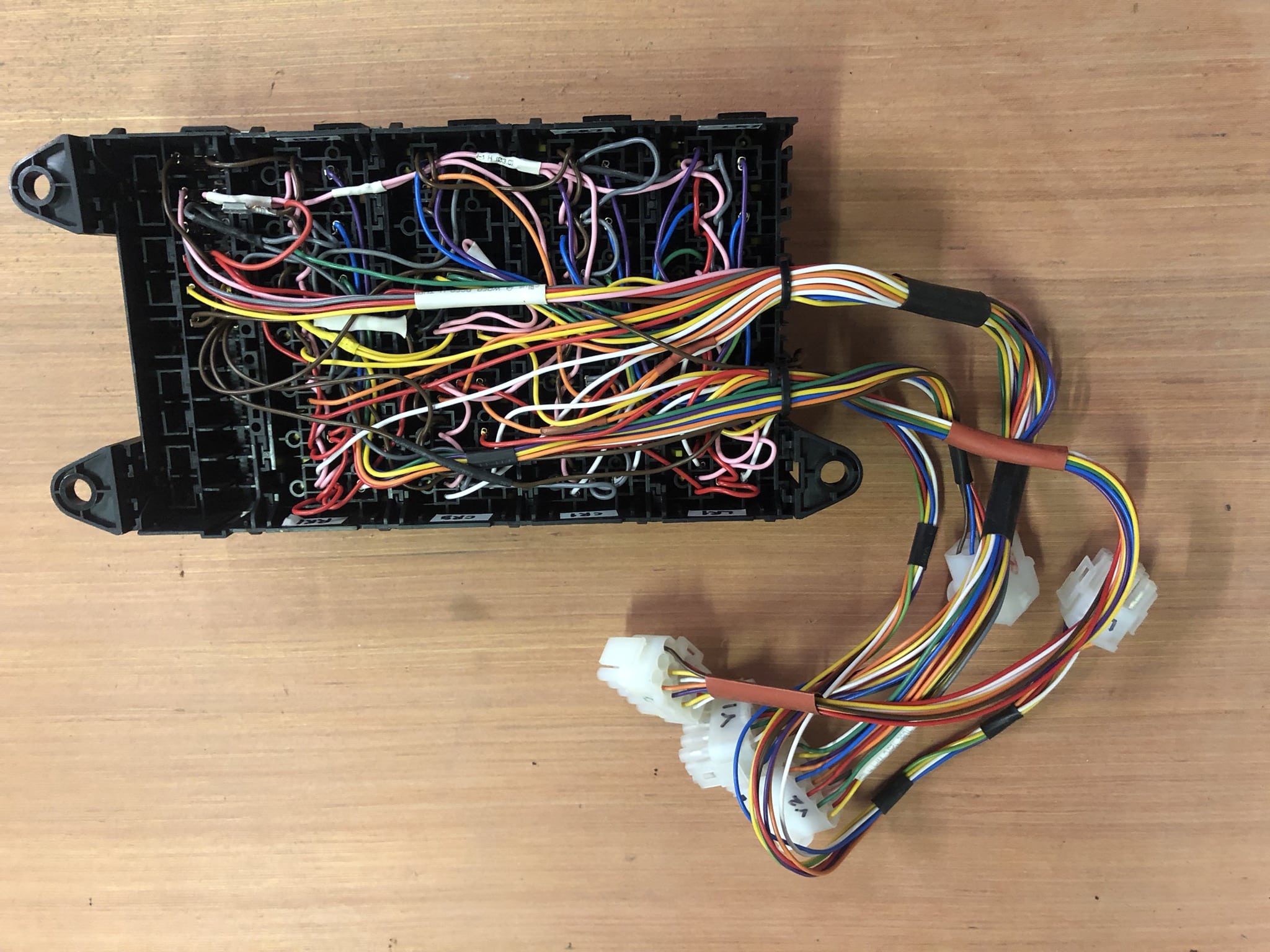
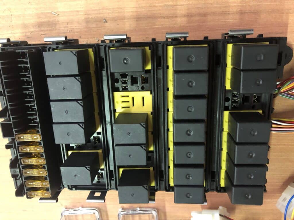
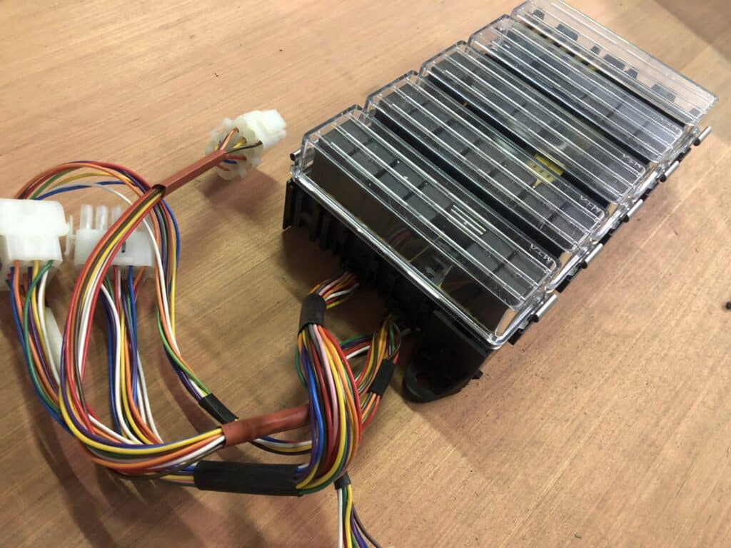
The final controller takes the form of four blocks of interlocking relay holders, a total of 28 relay positions, plus a bank of fuses (Fig. 1), and connects to the vehicle systems and the instrument panel using standard automotive multiway connectors (Fig. 2). Since the pins and matching receptacles are interchangeable between the mating plug and socket housings, it was possible to create a set of nine- and fifteen-pin tails which are not capable of being misconnected. It is possible to touch pins together when attempting to misconnect them, however, pins 1 and 2 are always ground and power, or are unused on bundles that do not carry power, and the other positions are arranged in such a way that connections which may momentarily touch pin-to-pin while attempting to mate the incorrect combination of plug and socket do not cause any damage. This is typically achieved by designating controller inputs as pins, and outputs as receptacles, thus ensuring that the only connections which can come into contact while attempting to make a misconnection are inputs.
A fault-finding and repair document was created once the design was finalised.
Summary
An electromechanical design was chosen to be the most cost-effective and reliable way to implement the requirements of a one-off controller for a bespoke solution, and represents a robust, automotive-rated solution which should be easily repairable using standard components for many decades.