
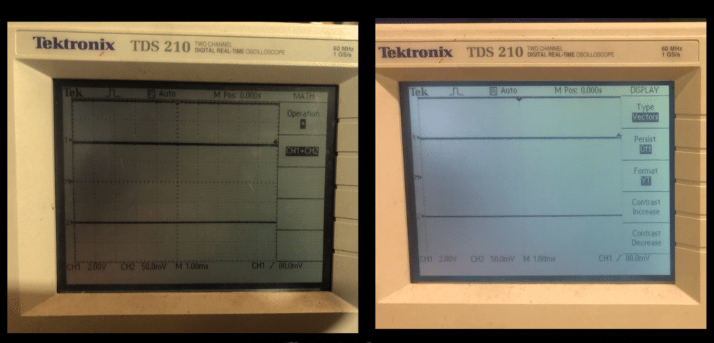
The screen on our Tektronix TDS210 was lacking brightness and contrast, so we thought it was probably the backlight.
After some trawling around online we discovered it was fairly easy to replace. The tube is obtainable from a few places online and it looked like an easy job.
Backlight Tube Operation
The tube in the TDS210 is a Cold Cathode Fluorescent Lamp (CCFL) .
Cold cathode tubes are part of a family of lamps that include neons, and the old Nixie tubes that pre-dated 7-segment LEDs for numerical displays. In many ways they are similar to the fluorescent lamps used for overhead lighting.
In this application, a high voltage excites a small amount of mercury vapour in the tube, to generate Ultraviolet light (UV). This UV is absorbed by a coating on the inside of the tube usually containing some form of phosphor. This re-emits it as visible light.
By adding various elements to the phosphor coating – typically rare-earths – it is possible to produce many colours, but backlight tubes are almost always white.
The tubes are non-polarised and run on AC, so opposite ends take it on turns to act as the anode and cathode. It’s therefore unimportant which way round you connect them.
Replacement TDS200 Backlight Tube
The CCFL in the TDS210 measures 100mm x 3mm diameter (4″ x 1/8″). I believe they are the same across the whole TDS200 range of oscilloscopes.
The tube sits along the left side of the display, and connects to the PCB in the instrument using a 2-pin connector. Various places online supply these tubes. Some are simple wire-ended parts, while others are already fitted with the wire and connector. On the face of it, you might think it would be easier and better just to buy the complete unit, and save on the soldering. I found this not to be the case because there is much more dismantling needed to fit a new tube if you have to unplug the connector. The tube also slides into a cylindrical fabric carrier that takes the light across the display. You won’t be able to simply slide the tube in if it already has the wires connected. You would have to somehow unstick the carrier and reattach it, which seems to me a good way to upset something which still works perfectly.
Tempting though it was to try and find a tube from a small UK business, I finally settled on my fallback for one-off and prototyping parts, which is RS components. They are rarely the cheapest, but I know I’ll get good service, and good customer service were it to arrive damaged. Plus I know I’ll get a VAT receipt.
This is the tube I used:
RS Stock No.: 534-9978 Mfr. Part No.: BF3100-20B Brand: JKL Components
According to its datasheet, this tube needs about 650V to start, and then settles down at about 250V 5mA once it gets going. The connections to the tube have rubber boots on them, and are heatshrunk. I’ve not seen everyone who fits these tubes bother to replace the heatshrink, but with something triggering at 650V located right at the front of the instrument beside the screen where any spilled water could easily get between the front panel bezel and the display, I understand why the manufacturer added that insulation. As far as I can see, it’s part of the safety design of the instrument, and should be repaired to the same standard as it was manufactured.
Summary Of Replacement Procedure
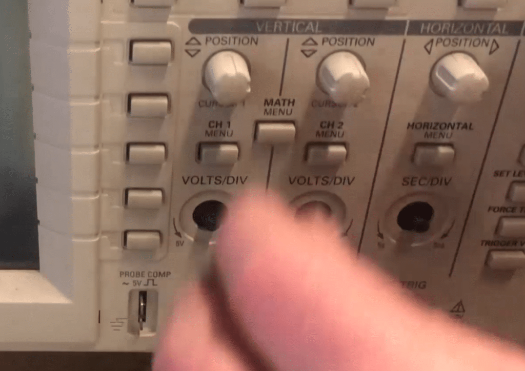
- Firstly, you’ll need to pull off the knobs. They just push onto shafts with flats and they are all the same. If you want to arrange them in order so the same one goes back on the same shaft it won’t do any harm. I didn’t, I just put them all in the plastic tray I keep handy whenever I disassemble anything. When I went to replace them I found that some were tighter than others, and I fixed that by swapping them around, so perhaps it is a good idea to replace them in their original positions.
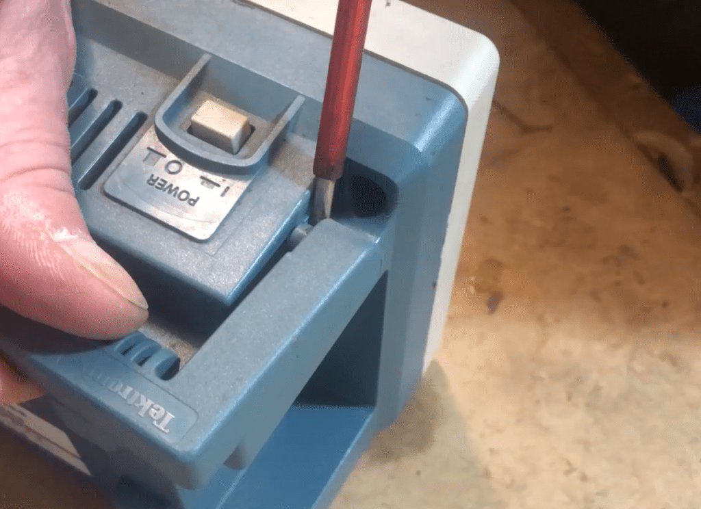
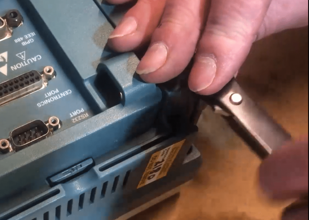
Don’t bother removing the power button on top. You won’t be disassembling the main oscilloscope. - The front panel is held on by two screws. They are behind the handle, so you need to prise one end of the handle gently out of its socket in order to remove it.
- The screws on mine were S15 Torx, and I happened to have a long Torx bit that fitted my ratchet. They’re not that tight or deep that you need one. A simple Torx bit for a screwdriver would work.
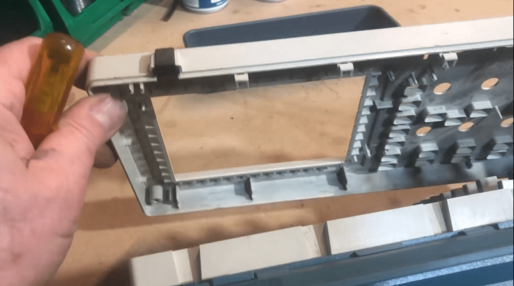
- The front panel now comes away along the top, and it is held in place along the bottom edge by small plastic latches which are tucked behind the folding foot. A bit of careful poking will disengage them and you’ll be able to take the front off. The buttons, which you didn’t remove, are all part of a rubber sheet, which will either fall off, or you can gently pull it off – if you want. If it’s stuck to the main board and it’s not in the way, you can leave it.
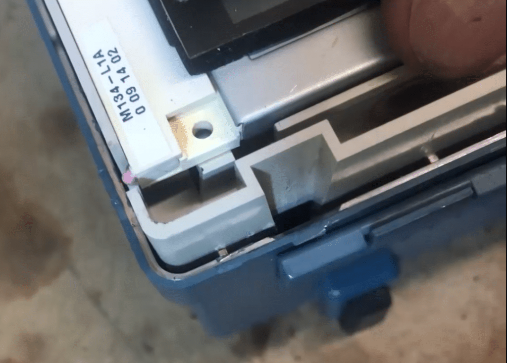
- The backlight tube is located to the left of the display and is easily spotted because it has a pink and a white wire. The display and backlight bare all part of one removable unit, which is handy to know if it ever fails. You can buy replacements. This display unit tucks under the PCB which holds the pots for the controls and the contacts for the buttons, and is held in place by two little tabs, one each side of the wire that connects to the backlight tube.
- If you carefully spring those tabs, you can lift up the edge of the display unit and slide it out a little way so it doesn’t drop back down again. It;s connected to the main board at the PCB end by a printed cable. There’s plenty enough slack on that just to slide the display unit out by a small amount without having to disconnect it.
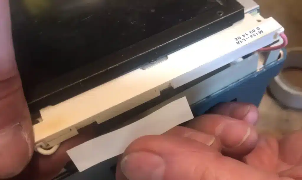
- There’s a cover plate on top of the backlight tube which is retained by three more tiny spring tabs. The combination of heat and UV from the tube is likely to have turned them brittle, and they will probably simply fall off when you lift up the edge of the display unit. It’s not a problem. The cover plate will stay on without them, or you can put a piece of tape there to hold it in place.
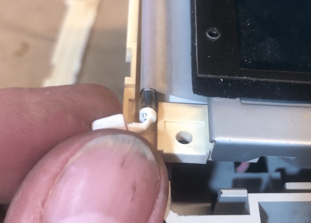
- Just pull the boots off the ends of the tube and cut the wires about halfway through the heatshrink, which will leave the solder joins on the ends of the tube and make a clean end to the wires.
- Now the tube can simply be slid out and replaced, and the wires soldered to the ends. I replaced the heatshrink with some white 3mm OD that I had in my box of assorted sleeving. You need to push it back up the wire way from the heat of the soldering, otherwise it will shrink, of course. It’s easy to forget. I didn’t even take the rubber boots off the wires.
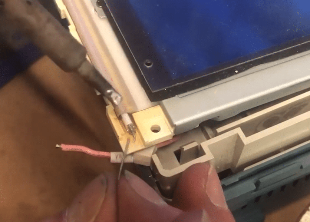
- Strip the ends and tin them. You’ll notice the insulation on the wires is some type of silicon. This is probably because the heat from the tube would tend to make plastic insulation brittle, which would impair it’s function as an insulator. In a high voltage application that wouldn’t be good. From experience, I have found that wire which have been exposed to long- term high temperature tend not to tin easily because the individual strands have oxidised. For that reason I turned up my soldering iron to a higher temperature because I’ve found that helps the flux to remove the oxidation better. The silicon insulation didn’t mind a bit.
- The wire ends on the tube need to be bent to right angles. With glass joins I always hold the wire near the tube with needle-nosed pliers, so the bending doesn’t stress the join. The wires on this tube were really quite soft and I needn’t have bothered. They just want a bend, and trimming so the final solder joint will fit in the rubber boot.
- The original connection to the tube was just an overlap, so all you have to do is melt the two tinned wires together, and then repeat for the other end. By the time you’ve done that, the opposite end will have cooled enough to pull the heatshrink over the end of the tube. You won’t get a heat gun on that to shrink it because that would cause damage, but the tube gets warm so it will shrink by itself into the final right-angle shape it forms when the boot is put back on.
- Arrange the wires to avoid trapping and push the display unit back in so it drops into place and latches. There’s a metal clip which you need to squeeze in order for the unit to slide back under the PCB. I think this is used to take up any top-to-bottom play on the display unit, so it doesn’t rattle.
Now try it out before reassembling it in the reverse order you took it to pieces.
The new tube will take some time to burn-in and achieve full brightness. I found half-an-hour did it.
Summary In Pictures
This is a simplified version of the procedure. Please use them in conjunction with the summary.
Summary Video
Further information will be found in the above summary.