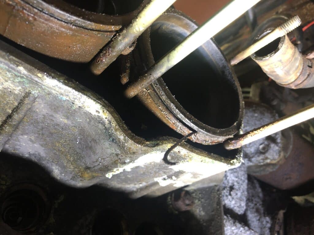
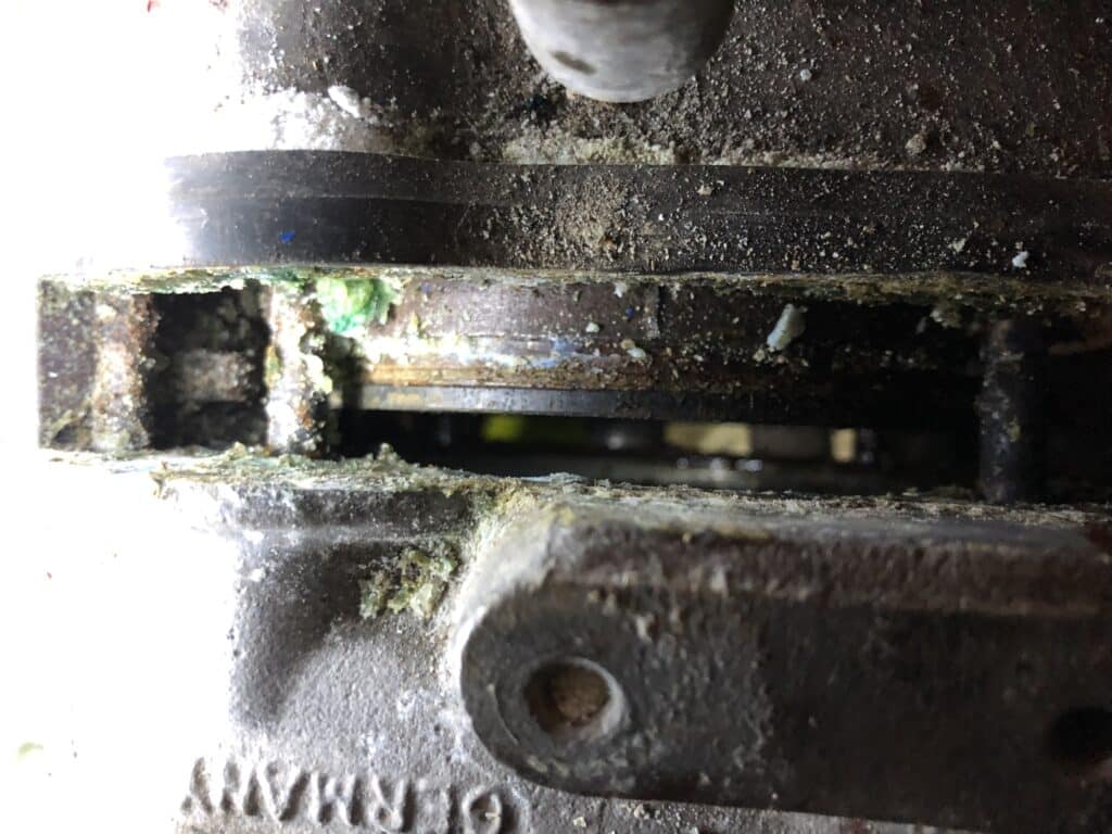
My VW Transporter T25 DG series engine had started developing white and green residue, especially underneath and around the black rubber gaskets either side of the cylinder heads. At some point it also began using water. I’ve had this vehicle since new in 1989 so no-one had messed with it except me.
This is caused by those black rubber gaskets failing, and sometimes other problems, which I’ll get onto later. To fix it you’ll have to take the cylinder heads off and do some work on them. With a bit of effort, and if you’re careful, you can do this with the engine in situ.
This is a waterboxer engine, so the cylinder heads are on either side of the engine ‘block’ which is really two halves bolted together, rather than a solid lump of metal. Replacement of these rubber water seals is a similar job to replacing a head gasket, but it can be tricky with an old engine like this one which I’ve had from new in 1989 because the whole thing will be full of corrosion and sludge,
I am assuming here that you are competent with mechanics and engineering – so I’m not going to describe basic things in great detail, but I will point out observations and tips which I’ve discovered can make life easier with this particular engine.
Although there is plenty of space in the engine compartment, you’ll have to remove a lot of things, probably more than you originally expected, simply to make enough room to work.
You’ll need to drain the coolant, but there’s no need to drain the oil unless you’re planning to replace it. Mine was new. The oil is all in the bottom of the engine and it’ll happily stay there.
Obviously, the exhaust and inlet manifold have to come off. I took the whole inlet manifold, complete with carburettor, off in one piece. You’ll have to disconnect all the pipes and vacuum advance, unbolt the throttle linkage and disconnect the wires that go to the manifold heater and the idle cut-off valve. Then you ought to be able to get the inlet manifold and carburettor off in one piece.
Note: I finished up replacing the carburettor, but that’s another story.
When you disconnect the spark plug leads it’s probably useful to make a note of where they go back. There is supposed to be a mark on the distributor housing to indicate cylinder 1 and the firing order is well documented elsewhere, but it’s just a pain having to look it all up, and the markings aren’t very clear at all.
The exhaust has to come off. I’d just refitted a new stainless steel exhaust system, so it wasn’t too bad, but there are a lot of clamps and bolts to undo. If you start at the rear of the engine (towards the front of the vehicle you can probably take the back parts off first, then the front, and you might get away with not having to remove the silencer, which is fiddly because it bolts to the engine mountings and it a pain to get at.
The cover plates underneath the engine which protect the pushrod tubes are held in place by the bottom exhaust nut. You’ll have to spring the tabs over the end of the studs to get them off. I managed to do the right-hand one without taking the oil filter off by undoing the rear one first and then letting the cover hang at an angle. Normally you’d just replace the oil filter anyway, but this was a brand new one.
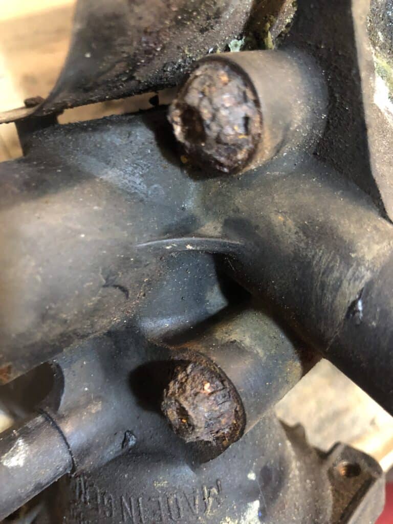
You’ll need to detach the water pipes from each head as well. Here you might have a problem. The left head (nearside) has a plastic thermostat housing attached to the back end of it. I couldn’t get that undone because the nuts were inaccessible and crumbling, so I decided to take the head off with the thermostat housing still attached and get it undone later. Since the thermostat housing is plastic there’s no option to heat them up.
There are two sensors on it that come off by removing a wire clip, plus the rubber hoses, which are really hard to get to. The wire clips on my sensors were very corroded, so I looked for new ones online and found they do plastic ones these days. They turned out to be much better.
One of those hoses connects to a long metal pipe that runs from the thermostat housing to the water pump on the front of the engine. That will have to come off too.
Water Pump
I was unable to get the bolts – well, technically ‘screws’ because they go into a threaded hole but don’t have a nut on the end – undone because they were seized. After a while I decided that this was no good, and the easiest thing would be to remove the water pump with the pipe attached and sort it out on the bench, as I had decided to with the thermostat housing.
I will probably one day want to replace the water pump (again) so I really want all the fixings to come undone easily. It’s not easy to get to the three 13mm nuts that hold the pump onto the crankcase, but they do come undone. You might need a box spanner for one of them because a socket won’t go around it.
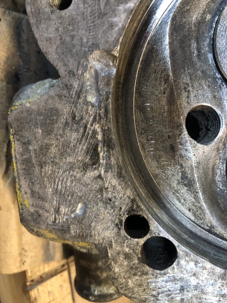
There is another metal pipe on a flange which goes from the water pump across to the right side of the crankcase. This has a flat moulded into ti to provide clearance where it goes behind the crankshaft pulley. I managed to get that undone but because the water pump is on studs you can’t pull it forward to get it off the studs without removing the crankshaft pulley. As we see later, I fixed that when I reassembled it.
Crankshaft Pulley
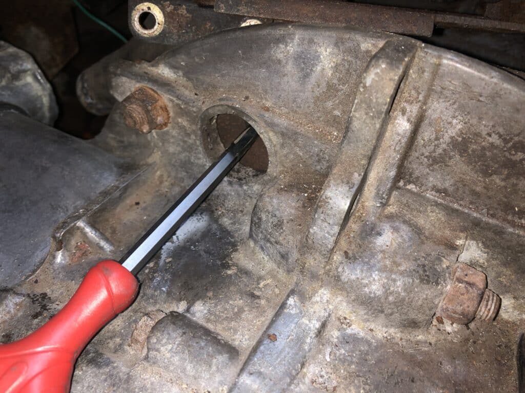
There’s a hole in the back of the engine bellhousing. If you turn the engine slowly you’ll find there is also a hole in the flywheel so you can jam it with a screwdriver or a drift to stop the engine turning while you get a 30mm socket and a big handle to undo the nut. Then you have to get the pulley off the engine. It’s jammed on a taper with a woodruff key. Warm it up with a blowtorch through the number-plate hole, avoiding the centre, and it will probably just lift off like mine did!
Eventually you’ll come to a point where there is nothing attached to the cylinder heads.
Undo the clips holding the rocker covers on by springing them downwards with a screwdriver, and put the covers and cork gaskets to one side. They’re not left and right-handed.
Now the fun begins, but before it does it is probably useful to understand how the ‘flat 4’ boxer engines work.
Flat 4 Boxer Engine Cooling
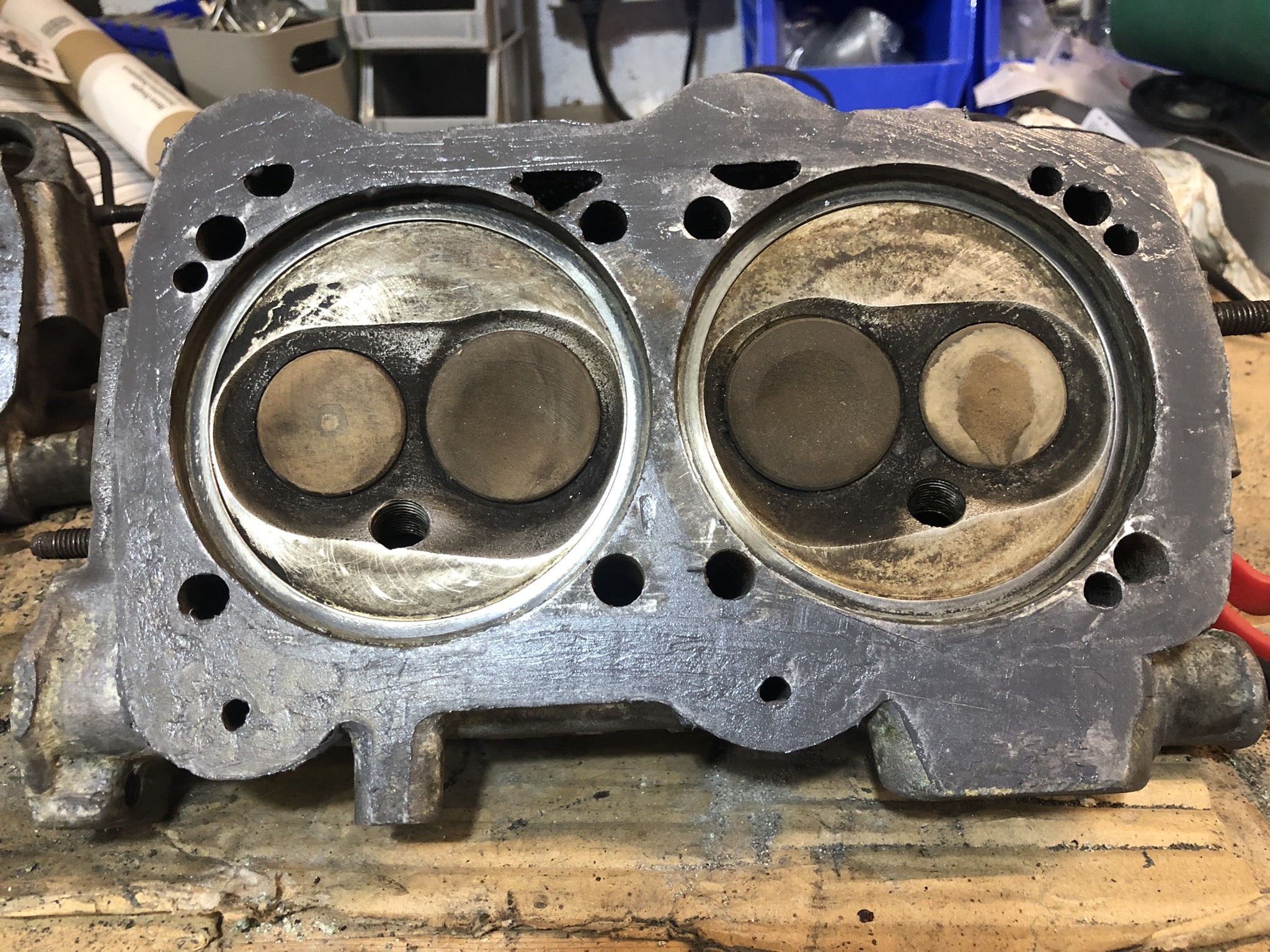
What is touted as a head gasket is not really a head gasket on these engines. A head gasket normally sits between the cylinder head and the crankcase, thus joining the valves and the spark plugs in the head together with the piston in the crankcase to make a complete airtight cylinder, and also lets water and oil circulate between the two, without allowing them to get mixed up.
The compression generated in the cylinders, coupled with the forces generated by the burning fuel/air mixture is very high. The pressure of the oil flowing between the two components is a lot lower, but still quite high, and then there’s the water flow, which is yet a different pressure. In other engines, all these effectively flow through holes in the head gasket, which is typically a flat sheet that’s compressed between the head and the crankcase, and the forces applied by the head bolts have to keep this seal tight enough so that nothing leaks between all the various channels that pass through it.
Our engine doesn’t work this way. The pistons on this engine don’t run in holes bored into the crankcase. They run in a metal cylinder, which is usually called a barrel. Water circulates directly around the outside of this barrel. The barrel sits in a groove in the crankcase at the bottom end, which makes a seal to keep the oil in the crankcase away from the water that circulates around it, and it sits in a similar groove in the cylinder head, which keeps the compression in the cylinder and separates it from the water. The piston rings make the other seal that keeps oil out of the top of the cylinder where the compression takes place.
The only place involving oil between the head and crankcase are the seals at the ends of the pushrod tubes, and there’s no oil pressure there, just crankcase pressure.
That’s enough for now.
Rocker Shafts & Pushrods
Undo the two 13mm nuts that hold the rocker shaft blocks onto the cylinder head. The shaft and the rockers all come off as one piece and can stay that way. I put them in the upturned rocker covers to keep clean.
Now retrieve the pushrods by pulling them out. You might have to flex the engine tins a bit to get them out. Clean the oil off them and mark them up. I wrote B1,2,3 and F4 on some bits of masking tape with a sharpie, so I wouldn’t get confused about whether ‘1’ was a the back or the front. Red for the Right-hand ones and bLue for the left-hand ones. It’s a convention I use often. You’ll find a lot of lighting wiring in the T25 which is Black/Blue and Black/Red for left and right. The German for Left and Right is Links und Rechts, which is handy.
If you wrap the bits of tape around the pushrods like flags it doesn’t matter if they are still a bit oily.
Be careful. The pushrods have a drill hole right through the middle to allow lubricant to flow between the ends, which is part of the hydraulic tappet system, so they’ll be full of oil. The pushrods are symmetrical, so you’ll want to remember which end was which. It’s easy to take them out, swap them from hand to hand and forget which end was which before you clean and label them. However, they’ll have acquired different coloured staining at each end if you ever get confused.
Now for the fun, or the scary bit, depending on how you look at it.
Head Removal
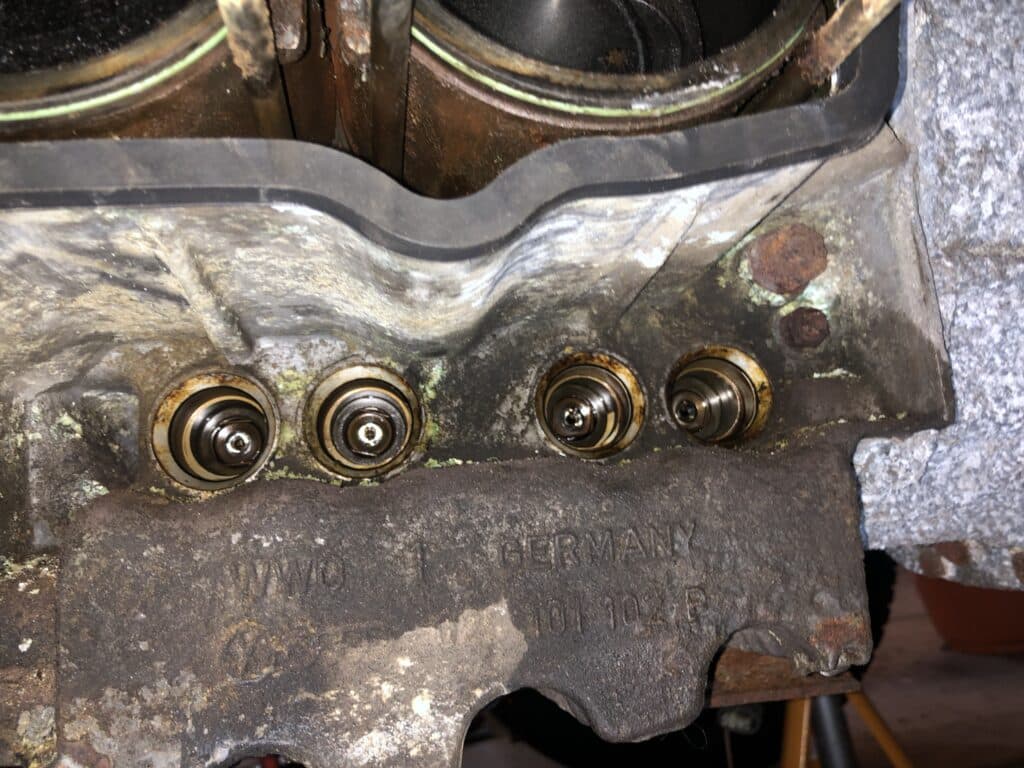
Find a 15mm socket and loosen the eight bolts holding each head to the crankcase. Four of these are exposed at the top, and the other four are in the oily area where the rockers were. They will be tight, but not actually very tight. You will probably find that they seem to move a bit and then feel ‘spongy’. They may even spring back. This is because these fixings are not head bolts, they’re studs and what you’re undoing is a blind nut on top of a relatively puny-looking stud. They don’t need to be any stronger than that. The springiness you feel you feel is the studs twisting. I spent a while wondering whether they were likely to snap off, and I did try heating up the nut, but in the end it made little difference. If you give them a yank they’ll probably go ‘crack’, and then be springy again. Once they’ve gone crack a couple of times they’ll come loose.
When you undo the lower nuts (in the oily part where the rockers were) you’ll probably find some water will run out, so just be aware.
There will now be a gap between the head and the rubber gasket, and the head will be free.
DON’T PULL THE HEADS OFF THE STUDS YET OTHERWISE YOU’LL FINISH UP HAVING TO TAKE THE ENGINE OUT
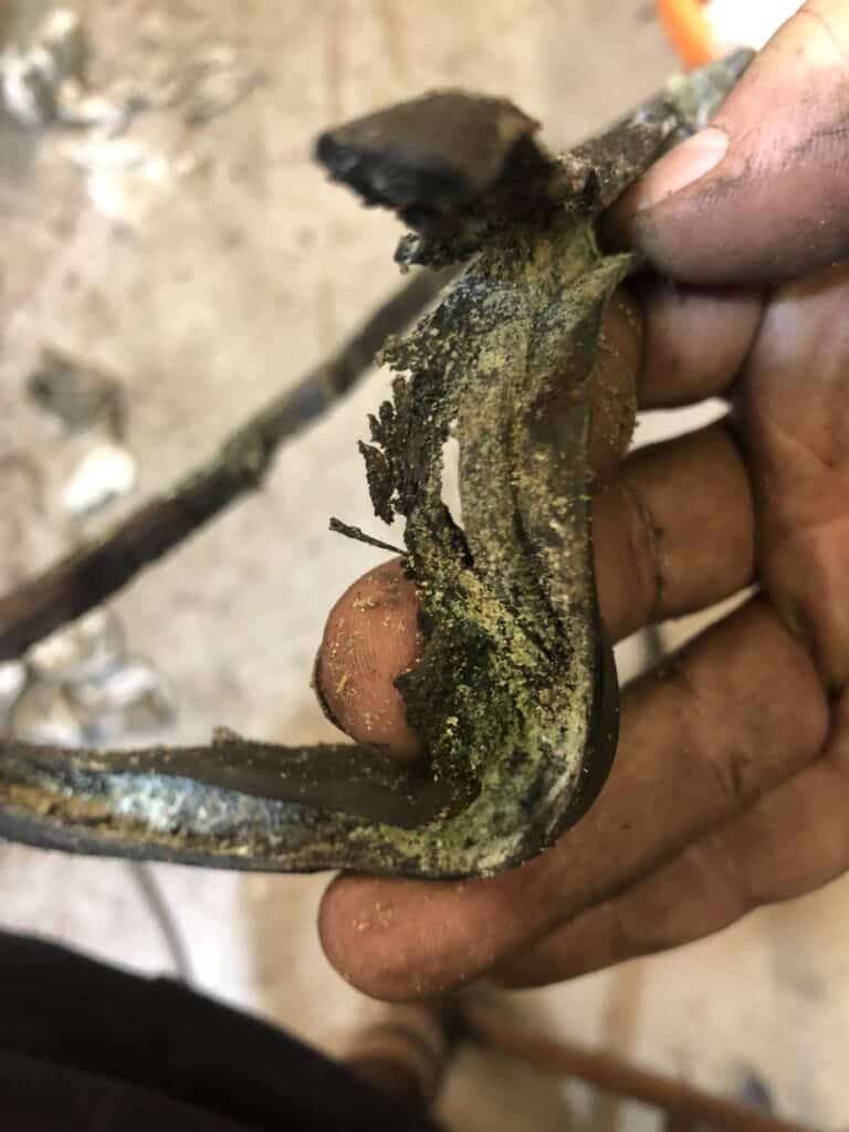
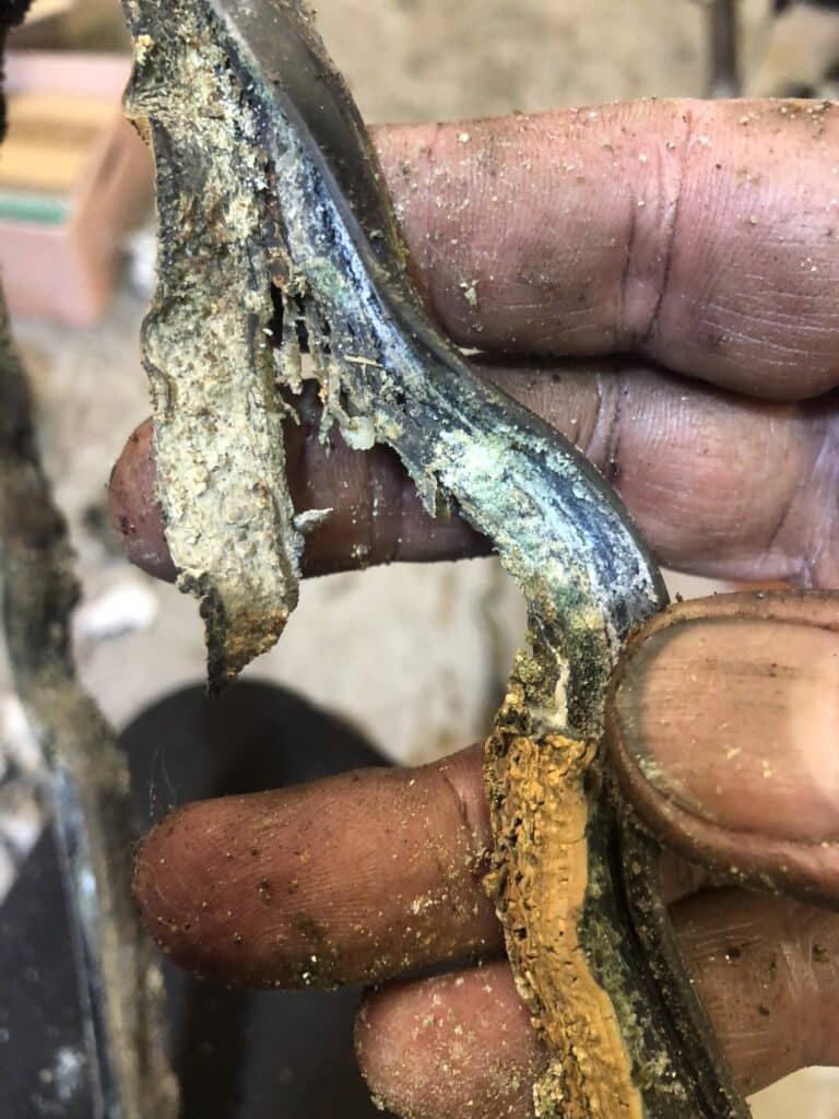
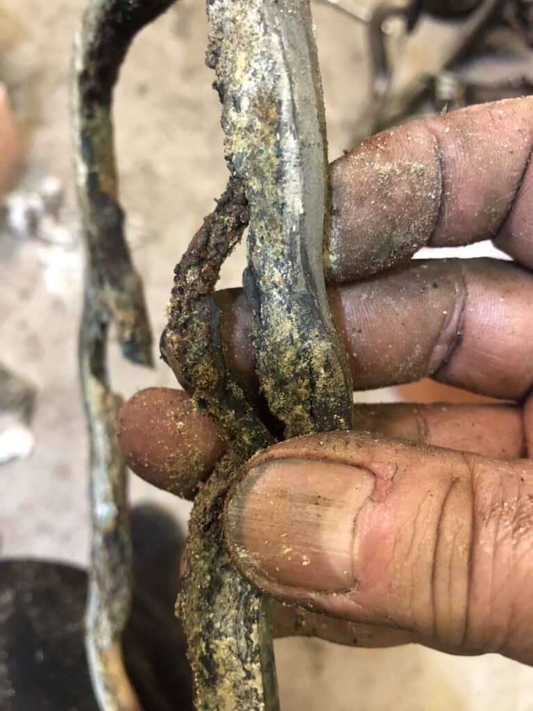
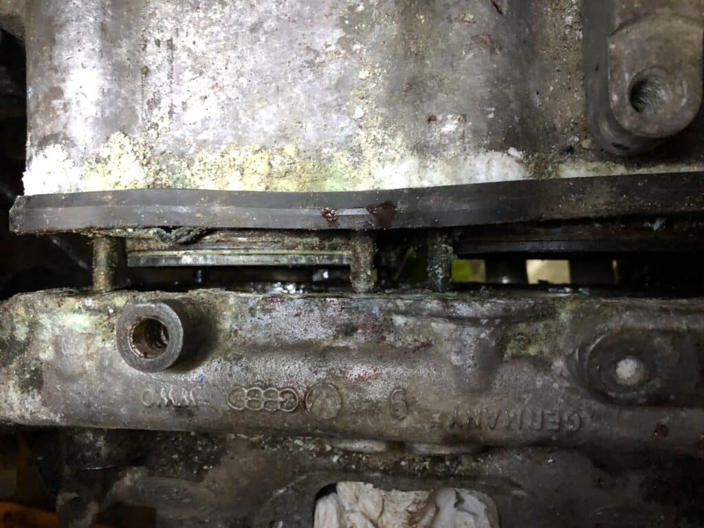
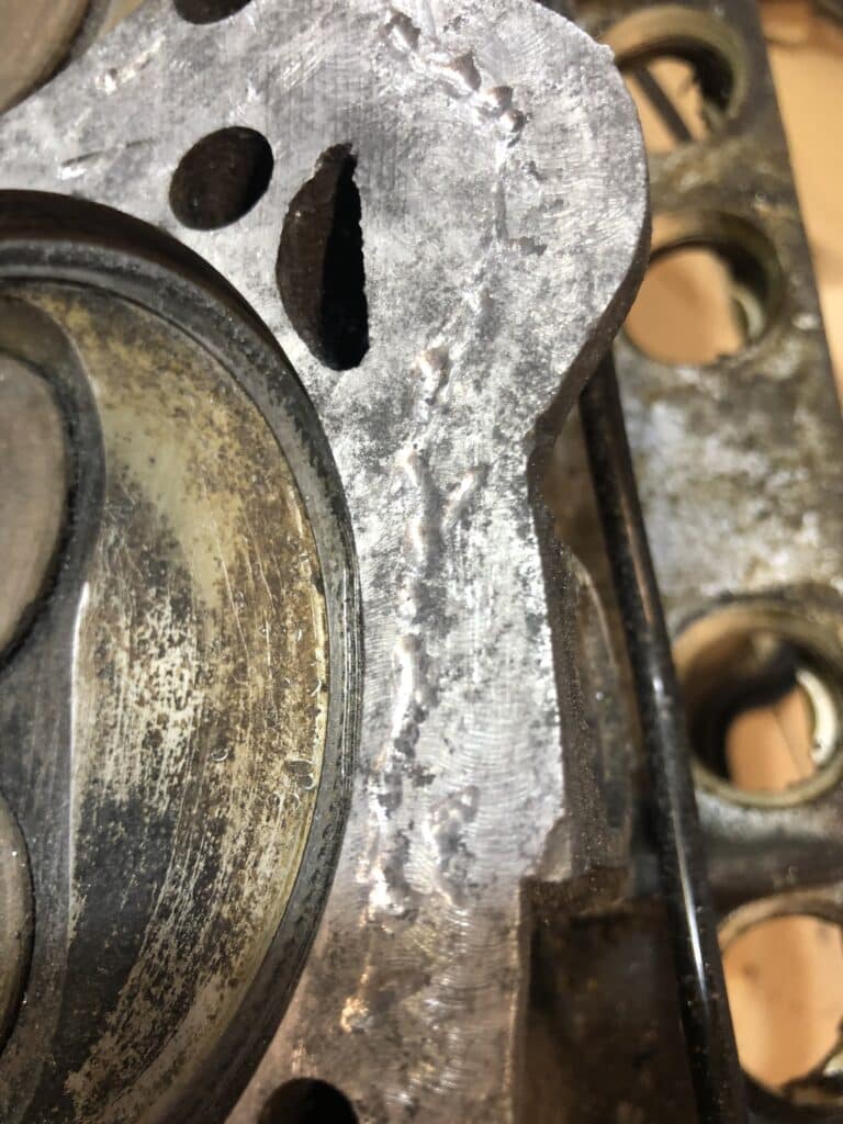
You’ll see how bad the water jacket seals are once you can pull them off. Mine were almost disintegrated.
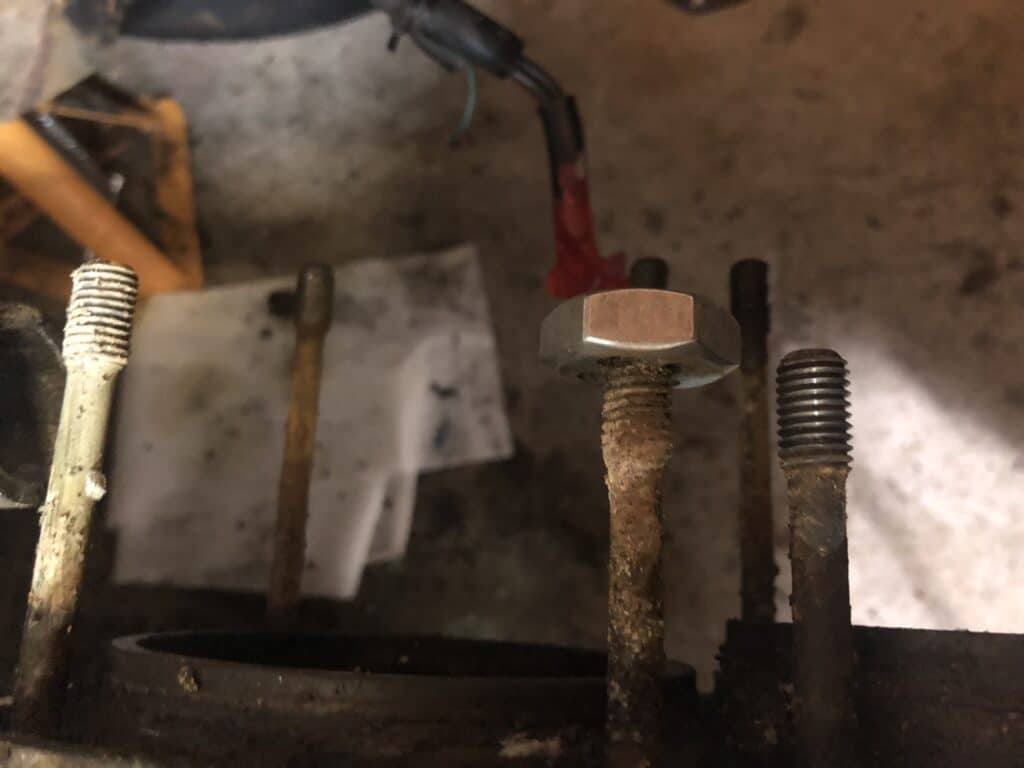
Now look at the nuts you took off. They have a flange and the threads are all full of water. This is why they’re blind nuts, because those studs are all in the space around the barrels where the coolant flows, and the nuts are the only thing keeping the water in the engine. That’s why water ran out when you undid them, and why they are not open nuts with a thread all the way through. It’s also why they were not especially tight but were almost seized on the ends of the studs with corrosion. There have water-sealing compound on their flanges, which you ought to get with the replacement water-jacket kit.
You’ll find the threads on the studs will probably be rusty and/or corroded. Ignore that for now, we’ll sort it out later.
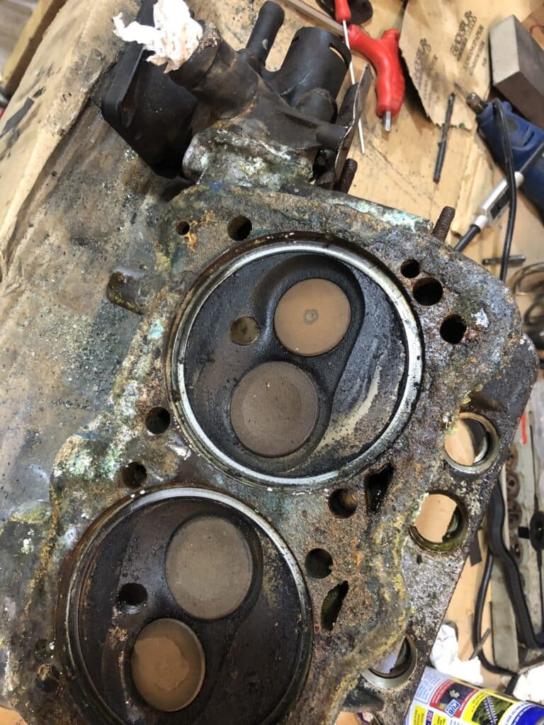
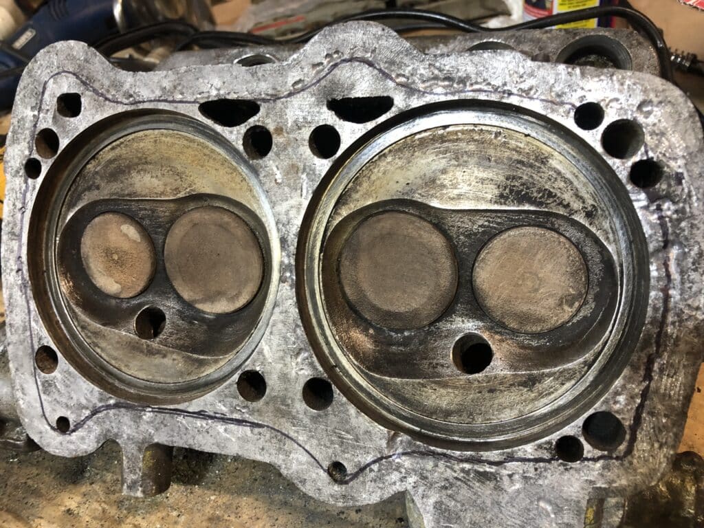
If you remember what we said: The pistons run in a barrel, which sits in a groove in the head and another at the bottom of the crankcase. You’ll find that the two barrels are stuck tightly in the grooves in the cylinder head. They’ve come out of the grooves in the crankcase because it’s nice and oily at that end, but the top end where we are is probably all corroded.
If you pull the head off with the barrels still stuck to it, the piston rings will spring out of the bottom of the barrels, and it’ll be nearly impossible to get them back.
Pushrod Tubes
Now is probably a good time to crawl underneath and collect the pushrod tubes. There will be a white rubber seal on either end of them. Sometimes it will stay on the end of the tube, sometimes it will be left behind in the tapered hole where the tubes fit. There’ll be new ones in the gasket kit.
Some people number these tubes, but VW recommend that you stretch the bellows so the tubes are a specific length before refitting them so that they compress, so it won’t matter if they don’t go back in the same places. They are interchangeable. We’ll do this later before we refit them.
Releasing the Cylinder Barrels
You need to get the top of the barrels free from the head before you pull it more than about an inch away from the block.
If you look carefully around the top edge of the barrel there are four lugs cast into it. With care you can tap a tapered drift between the lug and the head to separate them. You’ll probably need to do that in more than one place, but eventually you’ll manage to prise the barrel out of the groove. What you don’t want to do is damage the surface of the head, or break the lug off the barrel, which I think are cast and therefore brittle. It will require a lot of careful hammering and gnashing of teeth to try and prise it gently out while working on opposite sides (if you can reach the lugs) to rock it back and forth and break the corrosion.
It took me about an hour to do each side, but you do get better at it as you go along.
Finally you’ll be able to pull the head off the studs, leaving the barrels still nicely tucked into the crankcase. One stud on the left head was stubbornly refusing to go through the hole in the head block, it would come a couple of inches and then jam. Pushing the head back on and cleaning the thread helped, but I still had to wrestle with it a bit and tap it with a mallet.
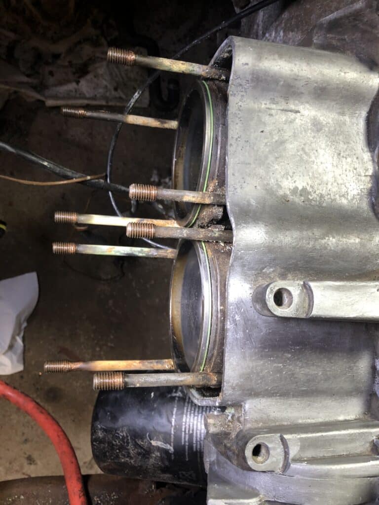
Once you get the head off you’ll see why this happens. The studs are actually quite ’puny’, they’re 6mm shafts with a sort of bulb on the end that has an M8 thread, so they look a bit like miniature honey dippers. When you think about how the engine works, and when we look at how to tighten everything back up you’ll realise that there really isn’t much pressure on the cylinder head, so the studs don’t have to be as substantial as those that have to compress a head gasket evenly.
Anyway, that bulb on the end of the stud was binding on something in the hole that goes through the head, but only on one stud. It’s worth cleaning out all the holes.
Cleaning and Repairing Heads
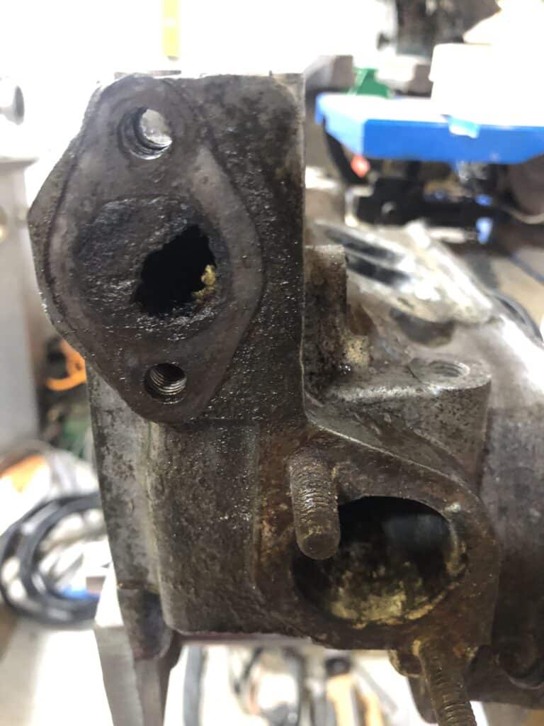
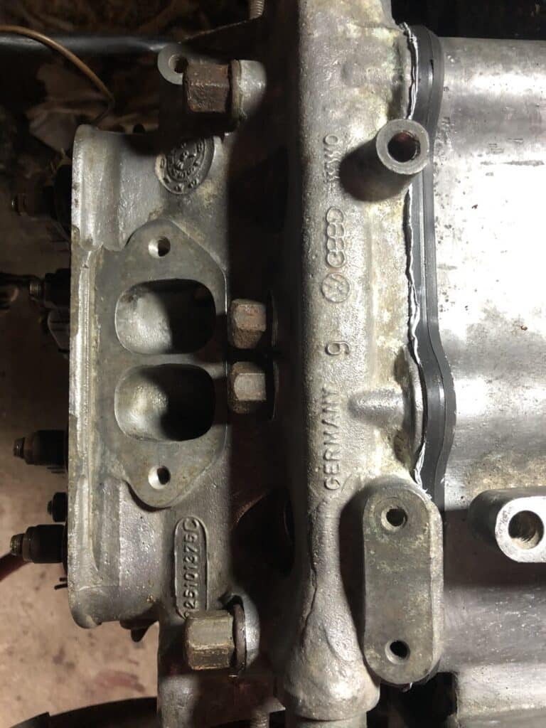
Now you’ve got the heads off and on the bench you can remove anything you couldn’t undo before. In my case this was the thermostat housing at the back of the nearside head and the connector flange on the front of the offside one. I had to grind the heads off the bolts on the thermostat housing. There was no way they were going to come undone. Then I could extract the rest of the bolt using a monkey wrench. In the end, however, I finished up buying a new thermostat housing because the 30-year-old one was a bit warped and didn’t fit back well.
I cleaned up the heads using engine degreaser, brake and clutch cleaner, and a few different sizes of wire brush in the battery drill. There was a thin layer of carbon on the heads and valves, but I decided not to make a big deal of removing it, and I was not intending to dismantle the valves. The engine was running absolutely fine before it leaked water, so I’m not going to disturb it any more than I have to.
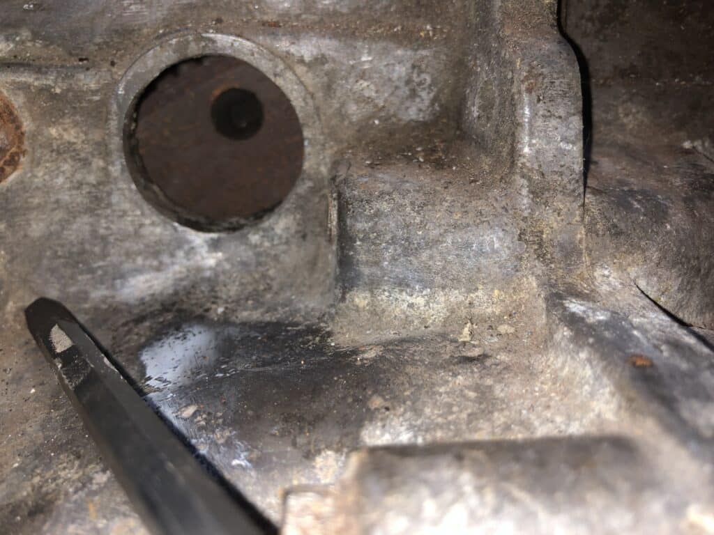
There is a water drain plug on the underside of each head, which is an M8 (6mm) nut headed screw. I took those out and replaced them with a new hex-headed (machine) screw. Don’t lose the copper washer in between the screw and the head.
Whenever I do anything like this with an engine I always like to think ahead to the next time I want to take anything to pieces again. With that in mind I like to replace old rusty nuts, bolts and screws. I really don’t like re-using old rusty fixings.
Now let’s get down to business. There were quite a few corroded patches on the head, and I used a Dremel with a small diamond arbor to clean out all the corrosion, and to grind out the marks until they were clean, and deep enough to fill in. Then I degreased the surfaces of the heads with brake and clutch cleaner, and thinners, before filling in the damage with ‘liquid metal’.
People think that the way to get a flat surface is to coat the head with much more filler than they really need and then spend ages sanding it all off. In reality you can use a little a possible and level it across the surface with a metal scraper. There’s no benefit in simply covering the whole surface with excess material. Although I did clean and repair all the corrosion, the only important areas are around the edge where the rubber seal fits. Try the new seals on and draw around them with a marker pen. Those ere the only surfaces that actually touch anything except the rims of the cylinders themselves where the new rings go. I just repaired all of it to be tidy.
That liquid metal takes 4 to 6 hours to ‘go off’ and 24 to 48 to cure properly, so that gave me time to turn to the engine.
Cleaning the Barrels and Studs
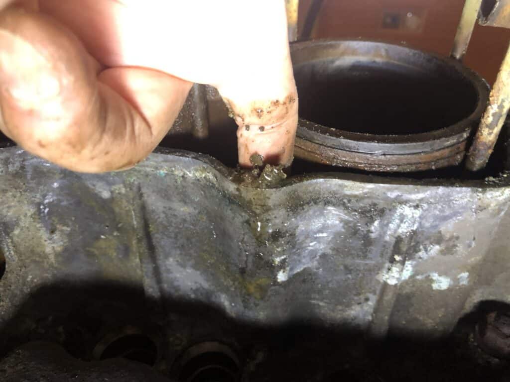
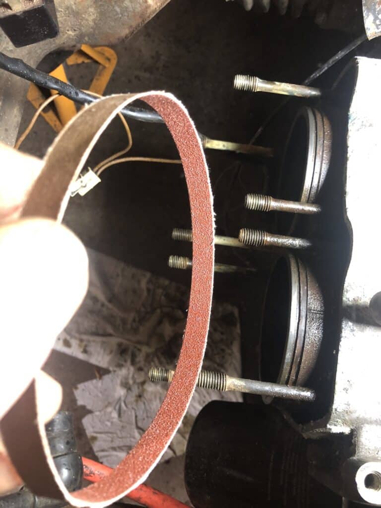
The outside of the cylinder barrels will undoubtedly be rusty. I used a sandpaper band that was designed for the powerfile to remove the corrosion around the edge. Tey not to let all the crud fall into the block. It will probably all stick the the sandpaper, but that space in the block is where the coolant goes – not the oil, so it;s not a big deal if some dust goes in. The outer edges of the cylinder barrels accept the new o-rings, and they slide into the ring on the head, which is why you want that part of head head to be clean and undamaged.
You’ll probably also find sludge in the ‘block’ below the barrels.
I used a hexagonal die to tidy up the corroded threads on top of the studs. These are handy because you can turn them with a box spanner or a socket where the isn;t space to swing an ordinary die handle.
Reassembly
Having levelled any damage on the heads that you patched up with liquid metal, you’ll now want to reassemble everything.
There are new seals in the kit, which includes o-rings for the bottom of the cylinder barrels where they join to the crankcase. You can’t get those out without pulling the barrels off the pistons, and then you won’t get them back on. I probed those o-rings and they were still rubbery, so it’s not worth disturbing them. Just seat the barrels back into the crankcase.
There are ring seals to go between the head and the top of the barrels, and sealing compound to squeeze around both the crankcase and the heads where the new rubber water seals sit.
There should also be sealing compound to put on the flanges of the head bolts to stop coolant escaping into the rocker cover.
When you tighten up the head bolts what you’re doing is squeezing the barrels between the head and the crankcase o-rings. The gap that remains between the head and the block is taken up by the rubber water seal. You’re in no danger of over-compressing that rubber water seal. This is why the actual flatness of the head surface is unimportant. Provided the rings seal the head to the barrels properly, the only other contact surfaces are to either side of the rubber water-seal, which has sealing compound on it as well.
Now it’s just a straight re-assembly exercise.
There should be flat gasket-type rings to fit in the cylinder head grooves to seat the tops of the barrels. The old ones are not very obvious so make sure they are removed. Seat the barrels carefully in the groove at the bottom end and check they sit at the same height as confirmation. Put sealing compound on surfaces of the head and block for the new water jackets. The line you drew on the head with a marker will help. Fit the rubber jackets, and offer the heads up on the studs. Don’t overdo the sealant, otherwise it will exude into a bead in the inside which might break off into the water system. You don’t need much. My kit contained nearly twice as much as I needed. The tops of the barrels should sit nicely in the grooves in the head. The top o-rings are on the outside of the barrel. The only ‘compression’ when you tighten up the head is the o-ring at the bottom end and the little rings in the grooves at the top. Combustion occurs in that top end where the ring is, and is also sealed by the green o-ring on the outside of the barrel. An o-ring used in that way performs incredibly well and the compression resulting from the head bolts is not part of the seal. The bottom end which sits on the o-ring is only separating the crankcase (oil) from the water around the barrel. It doesn’t deal with much pressure, and the compression resulting from the head bolts is only keeping the barrels from vibrating up and down. The rubber water jacket does get compressed which, along with the sealant, holds it in place, but it can’t be over-compressed because there is still plenty of gap even when the head/barrel/block assembly is all tight.
Pushrod Tubes
The old pushrod tubes are reusable provided they are not corroded. The manual will tell you what length to stretch them to in order to make a good seal. Remember to fit the new seals to both ends. I found that my tubes weren’t particularly compressed and were pretty much the right length anyway.
Remember to put sealer (mine was yellow) on the flanges of the head bolts before fitting them. This stops coolant from leaking out. If you have put a small amount of thread lubricant (assembly compound) on the studs too this will help stop water going up the threads and corroding them. If you ever want the heads off again in the future there may not be as much cursing and gnashing of teeth.
Rocker Shafts and Initial Adjustment of Tappets
When refitting the rocker shafts it can be a problem getting the pushrods to sit in the dimples in the ‘followers’ at the camshaft end. Remember you’re working horizontally. The best you can do as you tighten up the blocks is to check that the pushrods rotate properly. It’s best to loosen the adjuster on each valve as you tighten up the blocks, but keep the rockers pressed against the top of the pushrod so it can’t drop out. You’ll see if they start to get too tight and don’t rotate easily, and the rocker will be tipped at a strange angle if the camshaft end hasn’t gone in the dimple properly. All the lobes of the cam will be in different positions, so they won’t all finish up in the same places, but they should all look right and the pushrods should all rotate easily. At the end of tightening up the rocker shaft blocks, you effectively have a valve arrangement with zero ‘tappet’ clearance. That’s okay because they adjust very easily. If there is a big gap between the block and the head when the nut is getting tight the pushrod probably isn’t seated properly. All you can do to fix that is to loosen the adjuster and try to wave the back end of the pushrod around by holding the little bit that sticks out of the head, until you find the dimple, which is quite hard.
Hydraulic Tappet System
You now need to readjust the rockers. Until the pushrods and hydraulic tappets refill with oil and begin to work properly, the whole engine’s going to sound like a bag of bolts. The rockers don’t have a specific clearance because they are self-adjusting, but the usual initial setting is to put each cylinder at TDC on the compression stroke so both valves are closed, set the adjuster until it just make contact (without pressing it against any springiness) and then tighten it two full turns. That gives the correct clearances in the hydraulic system so it works properly once it fills up with oil. The only route for oil from the crankcase to the rockers is along the drill hole that goes right through each pushrod, and this forms an integral part of the self-adjusting tappet system. The ‘follower’ at the camshaft end is a bit like a pair of pistons in a cylinder with a spring .Since the rod sits in both the follower and the rocker and has no ‘loose’ clearance, the gap between the pistons in the self-adjuster at the camshaft end fills up with oil, taking up any excess clearance until the parts operate at a snug fit. It’s more complicated than that, but that’s the essence of it. What you are doing by setting an initial adjustment is altering the point at which the balance of pressures occurs. It’s a very forgiving mechanism and provided you don’t set it so tight that there’s not enough gap, or so loose that the adjuster can’t move far enough even when filled with oil, it will settle to a point where the oil escapes from the pushrod at the cam end and the rocker end at the same rate as it is replenished from the pressured oilway in the engine block. There is a drillway in the rocker that takes oil from the end of the pushrod to the rocker shaft, so the oil path is closed and in theory little leaks out between the rocker and the shaft provided it’s not worn. This therefore forms a self-adjusting gapless mechanism whose feedback loop is: “How fast can the oil escape from the ends of the pushrod?” If the gap is too loose the self-adjuster at the camshaft fills with more oil.
This is why they are noticeably rattly until the engine has been running for a while and the self-adjusters at the cam end have filled up with oil and taken up any slack, which might involve having to fill the pushrod drillway back up, especially on valves that have been sitting closed and whose oil paths have been under less pressure and probably emptied themselves out.
Oil that makes its way into the rocker box assembly for lubrication creeps back into the crankcase through the pushrod tubes. That is the only route back. There is no oilway between the head and block as there is no gasket there.
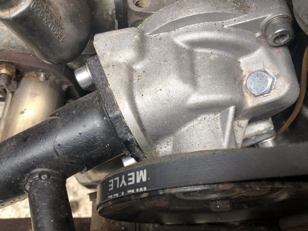
Water Pump Replacement
When I first removed the water pump I’d made my mind up that I wasn’t going to put it back on the studs, so I took those out. I re-fitted the water pump using socket head screws so that it can be removed next time without having to take the crankshaft pulley off.
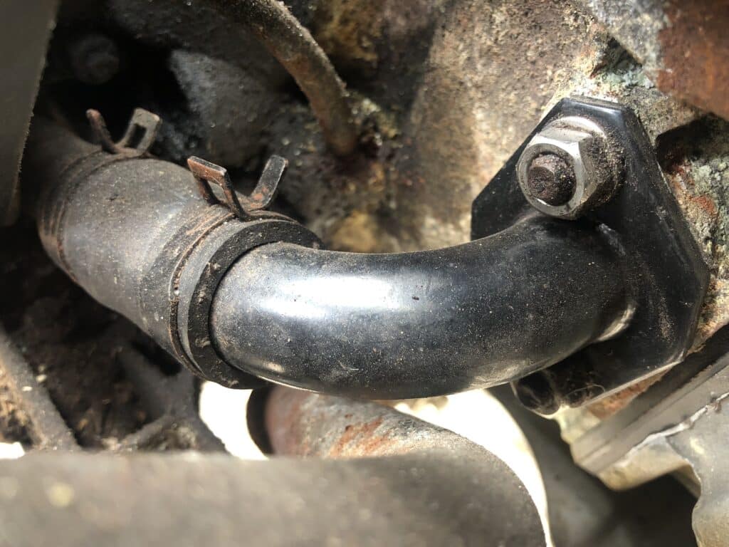
There is also a pipe which runs across from the water pump to the right hand side of the crankcase. That’s held on with two 13mm nuts, which again are a pain to get undone. This pipe is constructed in a similar way to the one that runs up the side from the water pump to the thermostat housing – it’s a metal pipe with a flange on one end, and a short segment of rubber hose to connect it to the other end. This metal pipe has two flat sections on it to miss the crankshaft pulley. It had some rusty sections, which I sandblasted, primed and repainted, and I also replaced the rusty old hose clamps with new carbon steel ones. One day I might need those undone and/or the pipe taking off, so there’s no point in leaving it as a dirty, oily mess.
I ran an M8 tap into the holes for the water pump where the studs came out, and a die on the threaded studs for the flange.
There was a new water pump o-ring in my gasket kit, but not ones for the various flanges, which didn’t make any sense. The elbow on the right hand side of that water pipe was plastic with an o-ring groove. I couldn’t easily get a new o-ring so I invested in a new aftermarket elbow, which was made of metal and had a flat flange and gasket instead of an o-ring.
I re-fitted everything with stainless steel bolts, screws and nuts, and used stainless steel washers between them wherever there was room. The rationale for this is simple. They don’t corrode. Yes, the assembly is now mixed-metal, but it was anyway.
Coolant System Reconnection
Just in case you didn’t label all the pipes: The thin hose from the head on the right hand side goes up to the circulation loop – NOT to the filler. The pipe from the bottom of the filler tank goes to the cap on the header tank. I spent a long time wondering why it wouldn’t fill up properly and trying to work out how it ever managed to when it was a pressurised system. Silly me.
Just for explanation: People talk about the top tank on the left side as being an expansion tank. There is no expansion tank in this cooling system. It’s designed so that any bubbles should find their way into that top tank. The screw cap has a valve which allows coolant to be pulled in from the filler tank behind the number plate when any air in the top tank contracts. It should be full of coolant. The valve in the cap is also a pressure release that operates at about 1bar (14psi) in the reverse direction to allow excess pressure to bubble back into the filler tank if anything ever boils, and that filler tank has some holes near the mounting flange to allow escape. which is why it has a maximum fill level.
It confused me for a long time and caused many headaches. I should have taken photographs before I disconnected anything.
Enjoy taking your engine to pieces! I usually think putting them back together again is much more pleasurable.
Other Notes
Waterless Coolant
Because I had taken my entire system to pieces, including removing the heater to fix a noisy fan, and replacing the radiator, it was empty of water and I chose to refill it with a waterless coolant (Evans 180). That wasn’t cheap because to refill the entire system takes a lot of coolant, but I believe it will be worth it.
Unlike water, this non-toxic coolant boils at 180C – hence Evans 180 I guess – and that means the cooling system is never under pressure. This means there’s a lot less stress on rubber hoses which I’ve not replaced, and on the old heater matrix. It’s also non-corrosive.
This is an improvement on older glycol-based ‘waterless’ coolants. It’s a little more viscose that water but carries heat better. If you have a high-performance engine and use it for racing this might be a consideration because it would be a greater load on the coolant pump, and a slightly lower flow.
This is an old camper van, not a Ferrari.
Because my company has the ability to print labels, I made one for the coolant tank which states that it must only be topped up with Evans 180, and not water. I’ve never had a problem with the coolant level dropping until the water jacket seals began to fail so I’m not expecting it to require topping up anyway.
Mixed Metal and Galvanic Corrosion
On the subject of Galvanic corrosion. Everyone has their own opinion on it, and usually have their own experiences to share. I can only tell you my experiences of mixed metal systems in engines over 40 years of messing with machines, and back up some of the things I say with scientific facts.
Almost all different metals will undergo what is called Galvanic corrosion, which ought to be capitalised because it is named after a person, in this case Luigi Galvini. This is really electrolytic corrosion.
Importantly, for electrolytic corrosion to occur it requires the presence of an electrolyte, which for our purposes is water. If you keep water out of the joint between the metals you can’t get electrolytic corrosion, and that’s another reason for using an assembly compound.
By using a water resistant compound we prevent the ingress of water into the thread, which prevents Galvanic corrosion. No water, no corrosion. It also stops the aluminium from corroding.
This means we can use any combination of metals, regardless of their electronegativity, so stainless steel and aluminium are fine. We got corrosion with ordinary steel and aluminium, which is why nuts are a pain to undo and studs get seized. I now go back to the copper washer on the water drain plug. Steel screw, copper washer, aluminium head. No assembly compound in sight, but also no sign of corrosion either. It’s seized up with the chalky white aluminium oxide, but that’s about it. We don’t get a lot of water there, even though it’s under the engine because it’s protected by the pushrod cover plate, and it gets hot.
Using a stainless steel fixing with a stainless steel washer means that the harder steel isn’t binding on the aluminium. When we want it undone neither surface will have corroded.
There is also a lot of talk about stainless steel being subject to galling, where the threads bind and jam. This occurs because stainless steel tends to be microscopically more rough than other metals, and generates a lot of heat when subjected to friction, which melts the material causing it to weld. To prevent this, experts suggest that the two threaded components have different hardnesses, so for example use A2 bolts and A4 (marine grade) nuts because, if there is any melting, the two don’t solidify at the same temperature and therefore don’t weld so easily. You won’t therefore get that problem when using stainless steel and aluminium, or cast iron. Having said that, the best way to avoid it is to stay away from generating a lot of heat – so don’t whang things up with an air gun. Take things carefully once they start to get tight.
I once saw someone on YouTube repeatedly winding an aero nut up and down a length of threaded rod with no thread lubricant using air gun until it jammed, and then bemoaning the poor performance of stainless steel. Well, what do you expect, especially when you generate that much heat? I know that plain steel doesn’t do that, but that’s not the way to treat stainless steel. It’s not a real-world scenario.
Paul stokes
Good info thanks ,who did you go to for the parts. As this is my next task
Steve
Hi Paul,
I don’t remember now. There are several specialist sites around that keep them. I’d be tempted just to look around for the best price.
You’ll want something like this:
https://www.customandcommercial.com/vw-engine–and–exhaust/wbx_engine–and–exhaust_1900cc–and–2100cc/waterboxer_cylinder_heads_barrels–and–pistons/german_quality_de-coke_set_waterboxer_t25_19cc-21cc_21253/
…because then you get replacements for everything that gets taken to bits. I think my set had a few small gaskets that I didn’t use, and I seem to remember I had to cut a couple out of gasket paper because they didn’t fit mine. I have a slightly different water pump and I believe the flanges were a slightly different shape.